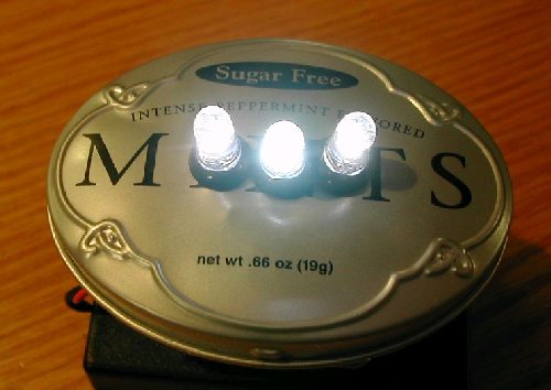
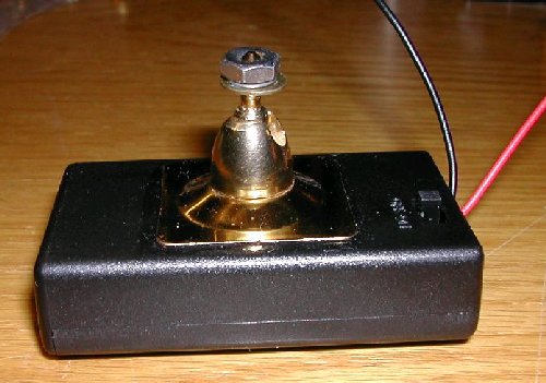
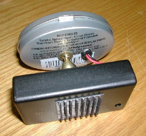
I ended up buying a 3 cell holder with switch from Mouser electronics, gluing an elbow/ball joint pivot from a desktop pen set I had pieces from to that battery holder, then bolting the pivot to a Walgreens tiny mint tin (the sugar free ones come in a small oval shaped tin). The LEDs rest on/in three rubber grommets in holes in the front of the tin (rather than mount them internally, it gives me a little freedom to "aim" each LED and easily control the light pattern).
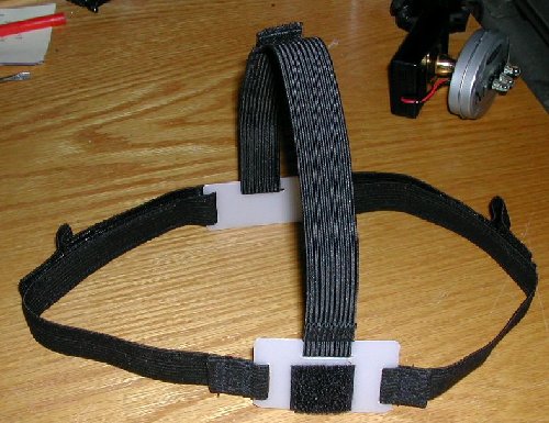
Velcro holds the battery holder to the head strap so I can remove the whole assembly and use it as "pseudo desk lamp" in a tent.
The circuit I settled on is simply the 3 LEDs in parallel, then that array in series with a 12 ohm dropping resistor (value is dependent upon choice of LED, e.g. current draw and voltage requirements, along with the type of batteries you choose). I set mine as a compromise between alkaline and Nimh AAA cells.
Here is the construction guide:
HOME-BUILT LED HEADLAMP CONSTRUCTION GUIDE
Front Assembly On
MOTIVATION:
Well, I fell in love with the idea of an LED headlamp when I first saw some of the commercial models out there in catalogs and stores. I also thought that the price on many of these was a little high, but even more important to me is that I KNEW that I could make one. Once I told myself that, I had to make one from scratch. I am sure that I put way too much time into this, so the cost savings was eaten up in the design, but for me, that part of the journey is fun !!
Before I get into the actual construction, I should discuss the circuit requirements first. The LEDs have their own requirements and I had a few of my own, too. If you aren't technical or don't care about this part of the analysis, move further down the page.
First off, the LEDs I bought are typical bright white LEDs with a fairly nice pattern that operate each at around 3.6 to 4.0 volts and require a nominal current draw of 20-30 mA for optimum performance. Right up front, this defines what is needed for battery voltage and operating parameters. I knew that I would need at least 3.6 volts to operate a single LED. Since weight was a factor, I decided to go with 3 AAA batteries (4.5 volts alkaline and 3.6 volts Nimh). I also wanted to be able to operate the headlamp with either alkaline or nickel metal hydride batteries, so I would need to test out my circuit before building the final project. I wanted to be able to remove the assembly and use it as a hand held lamp or just be able to set it down under tarp or tent. I also could have added more LEDs in parallel, but three were bright enough and I wanted my AAAs to last a long time.
I took 3 of my LEDs purchased and connected them all together in parallel and then experimented with different batteries and dropping resistors to see what would be satisfactory for my requirements. One cannot just connect the LEDs directly to batteries as this creates a situation where too much current could be passed through the LEDs, potentially destroying the LEDs. I tried different dropping resistors with both types of batteries to see what would work. With a multimeter, I was able to monitor voltage and current draw to see what would occur for different dropping resistors. Too low a value would result in the current draw increasing until it exceeded the design specs of the LED. Too high a value would result in a current draw that would not produce a good bright light. So for MY LEDs, I ended up with 12 ohms as being the best all around dropping resistor value. If you see other designs on the web, you may find other dropping resistor values.
The basic circuit I implemented looks like this:

        battery         resistor
---------|:|:|:----------^v^v^v--------------------------
|                                           |      |     |
|                                          LED    LED   LED
                                            |      |     |
/  switch                                   |      |     |
|                                           |      |     |
|                                           |      |     |
---------------------------------------------------------
PARTS NEEDED:
-
Note: my only connection with any vendors I mention here is as a satisfied customer. Look around - I am sure that these parts could be located
elsewhere.
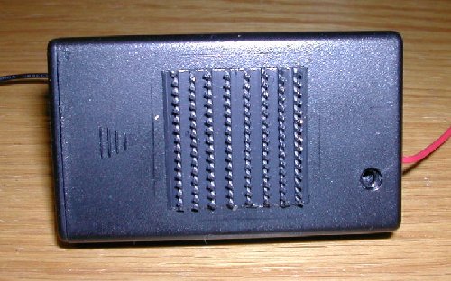
- 1 each Eagle Plastics Battery Holder part number 12BH431/CS 3 AAA holder with cover and switch from Mouser Electronics - catalog page is
http://www.mouser.com/catalog/cat_609/461.pdf - cost $1.24 plus shipping.
- 3 each bright white LEDs - I got mine from Larry Stephens Computer Parts on ebay at http://www.stores.ebay.com/id=96031 - these nominally
require 20 ma at 3.6 to 4 volts. I bought 10 from him at about $3.00 per LED. Caution - these should he handled carefully as they are sensitive to
damage by static electricity.
- 1 each small perf board with copper pads around each hole - I used a spare piece of board I had in my junkbox, but you can obtain a similar board
with 0.10 inch spaced holes and copper pads at Radio Shack for a few bucks - you can probably make 6-8 boards for the headlamp from one of
the boards you get from Radio Shack. Cost about $2.50 for 6-8 boards.
- 4 small rubber grommets for the three LED holes and the hole for the battery holder wires where the wire passes into the mint tin. I mounted my
LEDs from outside the tin, and just have them resting on the edge of each grommet. I figured if I mounted the LEDs from the inside, I would
have less flexibility in aiming the LEDs and making a nice pattern. The inside hole of the grommets should be able to accept both LED leads
without deforming them. Radio Shack should have these grommets. I had some in my junkbox already.
- 1 tiny mint tin - I used a Walgreens Sugar Free Mint Tin from Walgreens since it was a nice oval shape. A Tiny Altoids Tin or other tiny tin
would work. Use your imagination here, too, as there are other ways to enclose the board and LEDs - metal is not required here at all. The mints
in this tin are $1.59 from Walgreens.
- 1 each 12 ohm 1/8th watt resistor. A 1/4th watt would work here and the value may need to be determined with a test circuit before the circuit is
built as I described above. Radio Shack has assortments or small packs of 2 resistors for a particular value. Probably cheaper at a surplus parts
house, but maybe 50 cents for two at Radio Shack.
- 1 each desk pen set swivel. I used one from my junk drawer from an old pen set but WoodCraft Stores has a nicer but heavier swivel in their pen
making department for $2.99. I could not locate the swivel / ball joint on the www.woodcraft.com website, but they do have them in their stores.
- Epoxy for gluing the swivel to the battery holder. I used slow setting type as it gave me time to reposition and clean off any extra epoxy around
the swivel base. I let it dry overnight. I had this already and you probably have used epoxy to fix something around the house.
- 1 small heavy duty hook and loop (velcro) pad, about an inch square for mounting the battery holder and entire assembly to the headstrap. I had
this already but a hobby store or hardware store should carry them.
- 2 feet of regular hook and loop (velcro) material for the strap. Available at a fabric store or hardware store.
- 6 feet of 3/4 inch elastic (or your choice in size) for the headstrap. Fabric store.
- Nylon thread. Fabric store.
- 2 pieces of plastic, roughly 2 x 3 inches, for the front and rear of the headstrap. I used flexible plastic from sheet separators from a three ring
binder. The plastic or material you use should be flexible, light, and fairly easy to cut, since you will need to make slits in it for the elastic.
Velcro adhesive must adhere to this plastic. Be creative here, but a hobby store should have something.
TOOLS NEEDED:
- Sharp Scissors for cutting elastic and for sewing.
- Sewing machine.
- small wattage soldering iron - 30-40 watts should suffice. If you are NOT familiar with soldering, locate a family member, relative, friend, or
other hardware geek to help you with this - I am certain they will be glad to help.
- 1 foot electronic solder, typically rosin core - do NOT use acid core solder such as used in plumbing
- electric drill and drill bits for drilling holes in battery holder case and mint tin. I used a step bit as it cuts cleanly into the thin metal of the mint
tin without leaving a marred hole, but if you back up the tin with a small piece of wood, regular bits should suffice. A small hand drill or dremel
tool should suffice. Sizes will be determined by the rubber grommet size and swivel hardware.
- dremel tool or similar tool with cutting bit for sizing up the circuit board to the final size.
- Goggles or safety glasses for use while soldering, drilling, and cutting the materials.
- 1 pair of small needlenose pliers to remove and attach the mint tin cover while working on the piece.
- 1 pair of small diagonal cutter pliers for cutting component leads.
- Qtips for cleaning/mixing epoxy. I use a scrap of cardboard to mix the epoxy on.
- Exacto Knife or Utility Knife for cutting plastic.
- Emery cloth or sandpaper for smoothing board edges and roughing parts to glue.
STEP BY STEP INSTRUCTIONS:
ALWAYS USE GOGGLES OR SAFETY GLASSES DURING THESE STEPS
- eyesight is precious. If you screw up your eyes, here, you may not need a headlamp!!!!!
Battery Holder and Swivel Assembly:
Holder and Swivel
Inspect the swivel and see if the bottom (the part that will mount to the battery holder) has a screw adjustment of some type. If so, you will need to drill a hole in the inside of the battery holder to match where the swivel will be glued, in case that you need access to this screw to tighten it or loosen it for some reason. The swivel will be glued to the part that actually holds the batteries and houses the switch. I drilled a small hole to the exact center of the inside and there was even a spot available in the battery holder dead center for this hole. If you screw up and drill the cover, don't fret as you will be attaching heavy duty hook velcro to that part of the holder to attach to the headstrap and you can hide it that way.
Once the hole is drilled, you can prepare the surfaces for gluing.Rough the portion of those surfaces that will be glued together with epoxy and then clean with an alcohol swipe. Mix the two part epoxy (equal amounts of hardener and resin in a small amount should more than suffice) and attach the swivel to the switch side of the battery holder. Be careful not to apply glue that may spread and cover the adjustment screw. Applying epoxy to just the outside edges of the base of the swivel mount should suffice. Make sure the position is where you want it centered over the hole, use a qtip to clean up any extra epoxy around the base of the swivel and set it level somewhere for it to harden. Inspect it in a few minutes to see if the base has slipped any from your original position. If so, the slow epoxy should permit you to adjust the position. Set this aside to dry.
Headstrap Assembly:
Headstrap
Cut and trim the plastic pieces to your liking. The front piece should be roughly the size of the battery holder. The larger the piece of plastic, the more stable the velcro mount will be as there is a small amount of torque exerted by the weight of the battery holder and mint tin assembly, but we are thinking light here, so don't get carried away. Since the headstrap assembly is separate, you can always change its design at a later date for comfort, weight, etc.
Using an exacto or utility knife, cut three slits in each plastic piece to accommodate the elastic. Make these by actually making two parallel slits close together, then remove the plastic between the slits. The slits on the rear piece should be roughly 1/4 inch from the sides and top edges, but this is not critical. The slits on the front piece should be slightly less than 1/4 inch so that there is room for the velcro and also to provide a little stability on the forehead. The slits should not be so close as to weaken the structure of the plastic when the elastic is attached. Also, the slits should be about as long or a bit longer than the elastic is wide.
Using the knife again, smooth out the slits to reduce snags and cutting of the plastic into the elastic. Depending on your choice of plastic, a lighted match nearby the slit may smooth out any rough edges. You may also wish to round the edges of the plastic rectangles as well.
The elastic headband will be custom made to your head but I will describe how I made mine. I cut three lengths of elastic, roughly 17 inches each. I trimmed the elastic with sharp scissors and melted the edges with a lighted match.
Using the rear piece of plastic you made, route the elastic through a slit and then fold over the elastic twice and sew a seam (is my terminology correct here?? hehe) near the plastic piece. The folds should be on the outside of the strap so as not to irritate the head. As long as you do all three of these the same, you should be OK, since you don't commit to how the headstrap goes until it is attached to the velcro and the front plastic piece.
Once all three seams are done, you should have a plastic piece with three pieces of elastic dangling from it. Now, with the front plastic piece, thread all three pieces of elastic through the slits. If the fit is tight, you should be able to test a fit of the headstrap to determine how long the elastic pieces should be. We are going to sew velcro on the sides of each strap to give you flexibility in different size heads or to accommodate a hat or head warmer or even a fuller head of hair.
Don't sew on the velcro until you have the straps through the front plastic piece and have determined how long you want them to be. Again, a lighted match can seal the edges of the elastic to prevent unraveling. I sewed about a 4 inch piece of loop (the fuzzy side) velcro on the center outside of each strap, then made two small patches of hook velcro for each strap to accommodate some variation in size. One patch went on the end of each strap and one went about 2 inches inward from the end.
Once the headstrap is sewn and you are satisfied with the fit and the variations it is capable of, you can attach the loop portion of the heavy duty velcro to the front plastic piece. Swiping the plastic with alcohol can help clean the surface in preparation for the velcro adhesive.
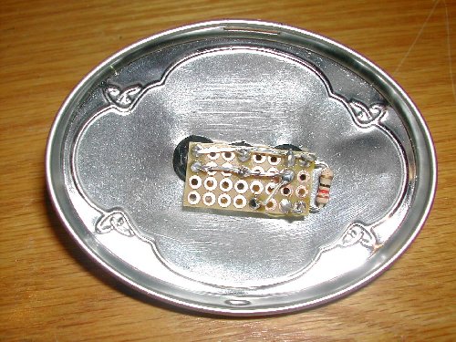
Rear of Tin Assembly:
Rear Assembly
Make sure the swivel assembly epoxy is thoroughly dry. Waiting overnight would be appropriate and would give you time to digest the rest of the instructions here if you have any doubts or questions.
Take the mint tin and carefully separate the two halves. Needle nose pliers or a small screwdriver can help here - the tin is sufficiently workable to permit re-assembly.
Using a tiny drill bit, drill a pilot hole in the rear of the tin. This hole can be dead center or perhaps a little lower but centered on the rear of the tin. Once the pilot hole is drilled, use a drill bit of the proper size to accept the screw portion of the swivel. If you are unsure about the size of the bit, line up the screw portion that will go into the tin along side a drill bit - they should have the same diameter. Drill this hole carefully, as the tin should mount tightly to the swivel here. Using a larger drill bit by hand, you can clean any burrs from the hole by twisting the larger bit gently in your hand into the hole from each side of the hole. Do NOT force the larger bit through the tin - you only want to clean off any burrs from the mounting hole.
Do the same for the wire mounting hole. I made my hole halfway from the swivel hole to the edge of the tin. This hole will need to accommodate the small rubber grommets you obtained. You may wish to experiment with a tin can to see what size bits your rubber grommets may need as it is hard to gauge what size you need from looking at the grommets. If your package of grommets came with a guide on hole size, you are way ahead of the game.
Install one rubber grommet in the hole that will accept the red and black wire from the battery holder. Once the grommet is installed, you can route the wires through the grommet and mount the rear of the tin to swivel. I used a flat washer on the outside of the tin between the tin and swivel and a lockwasher and nut on the inside. If your swivel did not come with a flat washer, lock washer, and nut, obtain one from your coffee can full of screws, nuts, bolts, etc. (You mean you don't have a coffee can full of hardware??)
Front of Tin Assembly:
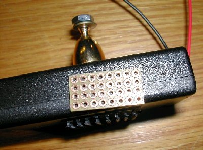
Holder and Board
Using the PC board and a dremel cutting tool, cut out a segment of circuit board that will contain an array of 4 x 8 holes. I used a dremel tool with a cutting bit (flat circular bit - use goggles), cut the piece of board from the larger board and then smoothed the edges of the board with emery cloth/sandpaper. The board will be used as a guide to mark where to drill the holes. I centered my holes vertically on the front of the tin and the horizontal spacing (how far apart each LED will be) was determined as follows:
To determine where the holes should be placed, use the circuit board as follows - for the type of LEDs we have here (T 1 3/4) I spaced the holes 0.30 inches apart - each hole in the board is 0.10 inch from the holes above, below, and to the side. Three LEDs spaced as shown in the photo along with a dropping resistor gave me a board that was 4 holes by 8 holes in size (about 0.40 x 0.80 inch rectangle). I left space at the bottom of the board for connections for the battery holder wires. A small brad or awl can be used to mark where the holes should go by pressing it through the board holes into the front or inside of the tin cover.
Using the same size drill and technique as for the grommet hole you made in the rear of the tin, drill three holes on the front of the tin for the
grommets and LEDs. Install the three grommets on the tin cover.
Lid and Board
First, we will mount the dropping resistor onto the circuit board. I mounted mine on the end of the board so that I could bend it outwards making the color bands visible. Taking the resistor in hand, bend the leads down so that they are perpendicular to the body of the resistor. You should now have a resistor with its leading making the shape of the letter "U". With the circuit board in hand, insert the resistor leads from the side WITHOUT the pads, pressing the resistor so that it is close, but not quite flush with the board. Bend the leads that have passed thru the board slightly outward to hold the resistor in place. Solder the leads to the pads on the copper side of the board. Use just enough solder to connect the leads to the pads. DO NOT trim the leads yet - we will use them for connecting to other components. The resistor should then be bent out to the side of the circuit board as shown as mine got in the way of the rubber grommets and the board.
Now, the LEDs will be mounted to the board and soldered. Hold the board to the grommets on the inside of the tin cover. We now insert one LED into the center grommet from the outside of the tin cover with the long lead of the diode going into the predetermined hole at the top of the board. The other lead should line up vertically with the second row hole in the board. While holding this position, you should have the other sets of predetermined holes behind its respective grommet and the dropping resistor off to one side. If everything looks fine, you can slightly bend the LED leads out at the board (upward and downward for the top and bottom leads respectively) to hold the assembly together.
Then insert the other two LEDs in the same manner, with the long leads of the LEDs at the top of the board. If you screw this up, at least make sure that all the leads are oriented the same, otherwise we will have one or two LEDs that will not work properly. With this assembly held together simply by the tension in the bent leads, you can now inspect the LEDs and the board for straight orientation and adjust if needed. The LEDs should rest on the shoulders of the grommets and be fairly straight and perpendicular to the front of the tin cover. The board should rest squarely on the grommets on the inside of the tin cover and the resistor should not contact the tin cover at all.
Once you are satisfied with the positioning, you may solder the 6 leads of the LEDs to the board. DO NOT clip the leads with the diagonal cutters yet.
Again, once the LEDs are soldered, inspect for proper orientation of the LEDS, board, and resistor.
Now, we will wire up the circuit. We are going to connect all three LEDs in parallel, then connect the dropping resistor in series with this parallel LED array, and then connect the LED/resistor combination to the battery holder wires.
Internal
Looking at the picture of the wired board, starting with the LED on the left, bend the two leads down to the right until they contact the center LED leads - wrap these two leads around the corresponding center LED lead, pressing the leads close to the board - it doesn't matter if the leads contact the pads on the board as long as the two leads from a SINGLE LED do not contact each other. The center LED should still have its leads up in the air. Solder those two connections and clip the first LED's leads at the connection with the diagonal cutters.
Now, do the same thing for the center LED - bend its leads to the right and make connection with the third and final LED leads. Solder and clip the center LEDs leads, leaving the final LED's leads up in the air.
Now, with the resistor leads that should be up in the air, we will complete the circuit board wiring. Bend the TOP lead of the resistor down until it connects with the top lead of the final LED, bending the resistor lead around the LED lead. Solder and clip the excess leads from the top of the final LED and the top of the resistor.
The bottom lead of the resistor will be looped and soldered to the pad next to where this lead comes out of the board as in the picture - this will make a terminal loop for us to connect the black / negative battery holder lead. Solder this lead and trim from the back of the board. If the board is too close to the tin, trim the resistor lead before soldering it to the pad.
The bottom lead of the rightmost LED should now be bent in a loop and soldered to a bottom row pad but leave a pad or two between this lead and the resistor lead. Trim and solder this loop. This terminal loop will be our positive connection to the red battery holder wire. This should complete the wiring of the board except for the wires from the battery holder.
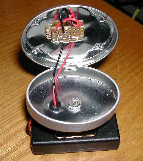
Tin Reassembly:
Take the front tin cover and re-attach the cover to the rear of the tin which is already attached to the swivel and battery holder. Needle nose pliers may help tighten the cover to the tin. Try the fit of the cover to see if it closes properly and stays closed. If the tin cover is too snug or pops from the rear, you can gently bend the cover and rear to get a satisfactory fit.
Assuming that we wired the LEDs properly with the long lead of the LED at the top of the board, we can now wire the battery holder wires to the board.
Taking the wires from the holder that should already be fed thru the grommet in the rear of the tin, feed one wire each underneath the board between the LEDs - it may be a tight fit if the board is snug against the grommets, but you should be able to get one wire between two LEDs and then tug it gently with needle nose pliers. Do the same with the other wire but route it between the other two LEDs.
After the red and black wires are routed underneath the board, tie the two wires together in a knot. This will provide some strain relief for these wires and take the strain off the connections we are about to make. The RED wire should be soldered to the terminal connected to the end of the dropping resistor. The black wire should be soldered to the terminal connected to the bottom row of LED leads. Wrap the wire lead around the terminal connection and solder for each. This completes the circuit wiring for the LED headlamp.
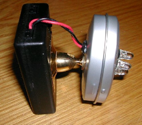
Side Assembly
Testing:
Turn the switch to the OFF position in the battery holder. Install three AAA batteries in the holder and install the cover to the holder (note - for some reason, these battery holders I received did not come with a screw to fasten the cover to the holder - find a tiny screw from your coffee can if yours did not come with a screw). A small piece of removable tape would work here, too. You can wait and install the screw to fasten the cover to the battery holder until after testing.
Turn the switch ON. If all the LEDs do not light, turn off the switch and inspect for good solder connections (the solder should be smooth and shiny and not contacting any pads or leads that it is not supposed to). If one or two LEDs light, then current is getting through the lit LEDs and thru the dropping resistor. One possibility if NONE of the LEDs light, is that the LEDs were installed with their leads upside down. If this is the case, you can simply switch the red and black wire to the opposite terminals. If this fixes the problem and all LEDs light, then you simply installed the LEDs upside down. To verify the LED orientation, you should be able to see a flat portion of the LED lens at the base of each LED with a magnifying glass. All the flat sides should be oriented the same way.
Holder and Velcro
If all works fine, you can close the tin and install the heavy duty hook portion of velcro to the rear of the battery holder, making sure not to cover the cover locking screw hole. Here is where I aimed my LEDs to give me an acceptable triad pattern by shining the light at the wall in a darkened bathroom. Gently, bend/aim the center LED down a bit so that it is below the center spot from the other two LEDs. Then the two outer LEDs can be gently aimed to complete the triad. Since the leads of these LEDs are one above the other on each LED, the safest direction to bend the LEDs is in a horizontal sweep, but since we have some flexibility here and since the board is held only by the LEDs, some vertical range of motion is available. Once you get the pattern to where you like it, you may wish to inject some epoxy into the rubber grommets and let it set. We do NOT want to always be bending these leads as they WILL break with repeated flexing and you'll end up with a two, one, ! or zero LED headlamp. Also, if you are uncomfortable with the LEDs sticking out from the tin, you may wish to make either some plastic protectors around the LEDs similar to the DiamondBack Moonlight (I haven't found anyway to aesthetically make one yet) or make a small closed cell box for the assembly when it is protectively stored.
The swivel should give adequate flexibility in aiming the light. If it doesn't quite aim down enough (mine won't quite shine vertically to the ground when I am looking straight ahead), you can adjust the headstrap down in front a bit.
Finished Product:
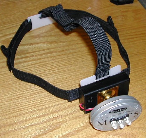
Finished LED Headlamp
TOTAL WEIGHT = 3.6 ounces, with headstrap and 3 AAA batteries installed.
Conclusion:
Comments, questions, suggestions, and recommendations are always welcome to improve this little guy. I figure my total cost, since I had some of the pieces in my junkbox, was around $17 to make this. I ordered parts for three since I knew my daughter would want one and that my wife should have one if she goes backpacking with us. If you have to go out and locate all the pieces, you might spend $20-$22 or so. Since the battery holder almost always needs to be ordered from somewhere, shipping would be a factor, too. If a group of folks wanted to go in together to order parts, it might save some on shipping if the group is all local. The circuit board could be obtained in the same order, too, along with the resistor.
My lamp gives me roughly 20-26 hours of bright light but is useable beyond that. It works nicely with alkaline batteries as well as rechargable nickel metal hydride batteries. Asembly time was probably 4-6 hours as I didn't keep track. I certainly took longer to decide just what I was going to do and how before actual assembly began.
Anyway, it shouldn't cost a 'mint' to build this. Mount the assembly to the headstrap and enjoy !!!
Return to: [ Top of This Page ] [ Make Your Own Gear Page ]